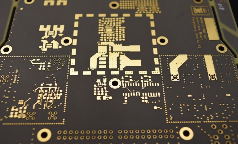
RF and Microwave Printed Circuit Boards
Experience the Benefits of Trusting MCL with Your PCB Needs
Radio frequency and microwave printed circuit boards require a special touch that your normal PCB supplier may not be able to handle. MCL is a trusted supply chain partner for PCBs. We can properly engineer and develop your RF PCB with high-frequency laminates with tight lead times and high-quality controls to ensure proper operation.
To address the needs of customers all around the world, MCL has become a leading RF and microwave PCB supplier that focuses on high-frequency PCB laminates.
You can trust MCL with your specialized products because we have the team, tools and experience in dealing with laminates that have specialized needs related to mechanical, thermal, electrical and other specific performance characteristics that are outside of the typical FR-4 materials.
Put your product in safe hands by trusting a top RF and microwave PCB supplier who focuses on tight tolerance requirements and delivering the support you need on time, every time.
Get Pricing and Lead Time Call 717-558-5975
Capabilities
- Quick Turn
- Prototype Quantities
- Production Quantities
- 2 – 44 Layers
- 35:1 Drill Aspect Ratio
- Maximum Panel Size – 24″ x 30″
- Blind / Buried Vias & Micro Vias
- Via In Pad with Fill Options
- (Conductive, Non-Conductive, Copper Plug)
- Controlled Impedance
Specs and Tolerances
| Outer Layer Trace / Space | .002″ / .002″ |
| Inner Layer Trace / Space | .002′ / .002′ |
| Minimum Drilled Hole | .002″ |
| Standard Drilled Hole | .008″ |
| Drill Aspect Ratio | 35:1 |
| Minimum Pad Size | .004″ |
| Minimum Feature to Edge | .010″ |
| Minimum Core Thickness | .001″ |
| Controlled Depth Drilling | YES |
| Sequential Lamination | YES |

General Guide to an RF PCB
Modern PCBs combine a variety of digital and mixed-signal technologies, so layout and design has become more challenging, especially when RF and microwave are in the mix for sub-assemblies. There are a few things to consider when looking at radio frequency PCBs, whether you’re working with us, another RF printed circuit boards supplier or designing your own.
First up is that the RF frequency range is normally 500 MHz to 2 GHz, though designs above 100 MHz will typically be considered RF PCBs. If you venture above 2 GHz, then you’re in the microwave frequency range.
RF and microwave printed circuit board designs have a few major differences to consider — differences between themselves and your standard digital or analog circuit.
In simplest terms, an RF printed circuit board is working with what’s essentially a very high-frequency analog signal. Your RF signal can be almost any voltage and current level at any point in time, as long as it’s between your minimum and maximum limits.
RF and microwave printed circuit boards operate on a frequency and pass signals within a certain band. Band pass filters are used to transmit signals in the “band of interest,” and anything outside of this frequency range is filtered out. Bands can be narrow or wide and can be carried via high-frequency carrier waves.
Get a quick free quote.

Special Materials and Equipment
RF printed circuit board suppliers and manufacturers require a mix of standard and specialty equipment for proper processing and manufacturing. Plasma etch machinery is one of the more significant requirements, because it can maintain high quality in the through-holes with minimal deviance.
Laser direct imaging (LDI) equipment is also commonly used for RF circuits, because it serves better than traditional photo exposure tools. You’ll want an LDI backing to ensure that board manufacturing maintains an extremely tight trace width, as well as front-to-back registration requirements.
How to Avoid Issues With RF & Microwave PCB Design
RF and microwave PCB with high frequency laminates can be difficult to design because of the sensitivity of the signals, especially compared to other digital signals.
Here are a few things to consider that ensure your design is efficient and minimizes the risk of failures, signal disruptions and other intrusions.
- RF and microwave signals are very sensitive to noise — much more sensitive than very high-speed digital signals. That means you’ll need to work to minimize noise, ringing and reflections while treating the whole system with care.
- Return signals take the path of least inductance — ground planes underneath your signal will make it easier to guarantee this path.
- Impedance matching is important. As the RF and microwave frequencies move higher, tolerance becomes smaller. Often, your PCB driver will need to be fixed, such as at 50 ohms, and that means 50 ohms out from the driver, during transmission and sending to the receiver.
- Transmission lines that bend due to routing constraints should use a bend radius that’s at least three-times larger than the center conductor width. This will minimize characteristic impedance.
- Return loss must be minimized, whether it’s caused by signal reflection or ringing. A return path will always be found, but your design should guide it and prevent bleeding of the return through the PCB’s many layers.
Use of High-Frequency Laminates
Laminate materials used in the fabrication of RF printed circuit boards add a layer of safety and protection for all of your equipment. These materials can help your equipment with all three common types of heat transfer: conduction, convection and radiation.
Thermal management is a top concern for all PCB applications in any industry, but especially in the cases where high frequencies are being used.
Finding the right high-frequency laminate for your PCB requires discovering a wide range of characteristics and determining how to combine them into a single picture. It’s a complex puzzle where you have to determine tradeoffs between multiple options and use cases.
You should choose your high-frequency PCB laminates based on how well they fit your applications, giving special attention to a few important characteristics:
- Coefficient of thermal expansion (CTE)
- Dielectric constant (Dk) and its thermal coefficient
- Smoother copper/material surface profile
- Thermal conductivity
- Thickness
- Flexibility for conformal circuits
Contact MCL for Your RF PCB Today
We recommend you speak with the experts here at MCL to learn more about these high-frequency laminates and get a better understanding on the selection process.
You’ll also avoid potential hazards by working with a leading RF printed circuit boards supplier. We can make sure your laminate has the proper thermal conductivity for those high-power microwave amplifier applications, but also ensure you have a low dissipation factor in order to reduce circuit insertion losses.
Every order, regardless of size, receives the utmost attention to detail throughout the entire process to ensure all customer expectations are met. Every order is produced within the strict guidelines set for by our customers.