Jump To:
- How to Measure PCB Temperature
- How Much Heat Can a PCB Stand?
- Common Causes of High Heat in a PCB
- How to Prevent High Temperatures in a PCB
- Contact MCL for All Your PCB Needs
Temperature is an important element of safety, reliability and performance in printed circuit boards (PCBs). High temperatures can quickly lead to malfunctions and permanent damage.
Several circumstances can introduce heat into the workings of a PCB. A component mounted to the PCB might produce excessive heat. An external element — for example, another component in a complex system like an aerospace system or medical application — might generate excessive heat. Heat might build up in the PCB because of inadequate ventilation. Or during PCB assembly, the heat produced during drilling and soldering might cause undue thermal stress on the components and lead to defective boards.
Whatever the reason, engineers need ways to manage heat to ensure that PCBs can survive the high thermal stresses they will inevitably encounter. What are some effective PCB heat dissipation techniques and ways to prevent PCB temperature rise? We’ll answer these questions in more detail below.
Why Is Monitoring PCB Temperature Important?
Monitoring PCB temperature is critical because high temperatures can alter the structure of the PCB and diminish its performance or cause it to break down.
PCB temperature measurement is also critical because the problems that result from high temperatures do not remain localized. They can quickly spread to other components of the PCB and cause a cascade of malfunctions and damage.
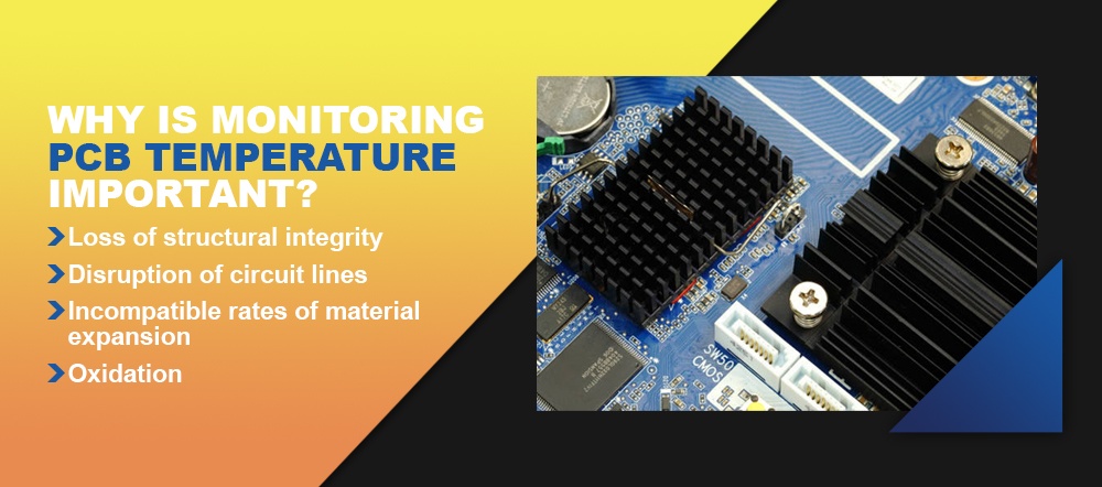
Excessive heat in a PCB can cause the following types of damage:
- Loss of structural integrity: Excessive heat can damage the integrity of a PCB. The layers of a PCB are highly sensitive to fluctuations in temperature, and when they get too hot or cold, they expand and contract. Excessive heat can lead to warping in the lengths, widths and thicknesses of different PCB layers.
- Disruption of circuit lines: Excessive heat can result in circuit damage as well. Circuit lines expand and change shape when they overheat. Once this happens, the circuits become susceptible to frequency shifts, distortions and straight losses. Their conductor impedance can also shift from its standard value of 50 ohms. Millimeter-wave circuits and microwave circuits, in particular, have tiny, delicate components that can easily sustain damage if they expand and deform at high temperatures.
- Incompatible rates of material expansion: The detrimental effects noted above are compounded by the fact that different materials expand at different rates. A PCB has two basic types of layers: dielectric layers and conductive metal layers. Because they contain different materials, they expand differently in response to heat. So an overheating PCB may experience further damage as the different types of layers pull apart.
- Oxidation: Oxidation of PCB components is also a concern at high temperatures. Exposed dialectic material in PCBs does not have protection against oxidation if it does not have a protective laminate coating. In that case, the material may rust after exposure to high heat. Loss of transmission lines and a higher dissipation factor often result.
How to Measure PCB Temperature
Before you measure PCB temperature, it’s essential to determine the primary heat source in the PCB — typically the microcontroller or microprocessor — as well as to locate the temperature sensors.
It’s also necessary to find the ground (GND) pins, which are usually attached to the substrate of the heat source. A large percentage of the heat generated in a PCB moves to the temperature sensor through these GND pins. Because the pins connect to the substrate, they have the least thermal resistance of any component of the PCB between the temperature sensor and the heat source.
Once you have these pieces of information, temperature monitoring can begin. PCB temperature measurement typically involves three different steps:
- Place a ground plane between the temperature sensors and the heat source.
- Connect the GND pins of each temperature sensor to the heat source’s ground plane.
- Make sure the temperature sensors and the heat source remain close to each other on the PCB.
Following these steps will allow you to measure the temperatures of the primary heat source — and thus of the PCB as a whole — with accuracy and precision.
PCB Temperature
PCBs are typically defined as high-temperature if they can withstand a temperature limit of 150 degrees Celsius. Some high-temperature PCBs may be able to withstand even higher heat. Still, boards manufactured from materials with less heat resistance will be able to operate safely only at much lower temperatures. High-temperature PCBs are becoming more and more common in applications such as automotive and industrial applications where extreme temperatures are part of the working environment.
Materials with optimal thermal properties provide reliable resistance against the effects of high heat, whereas some materials stand up less reliably to high temperatures. The glass transition temperature (TG) metric helps indicate this resistance. For instance, FR-4 has a TG of about 135 degrees Celcius.
Common Causes of High Heat in a PCB
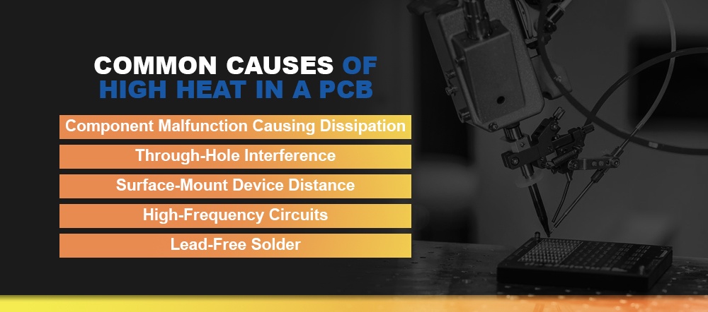
1. Component Malfunction Causing Dissipation
One common cause of high heat in a PCB is that one component within the PCB malfunctions and dissipates, failing to generate the amount of power it typically produces. When this happens, the surrounding components have to generate more power to compensate. Generating more power leads to the risk of overheating.
2. Through-Hole Interference
Through-hole components and heat-sink components are the components of the PCB that supply power. They generate heat and dissipate it into the air. If a heat sink is soldered incorrectly, or if a different component of the PCB is interfering with the through-hole, the other components will generate more heat than usual to compensate. This scenario also leads to a risk of overheating.
3. Surface-Mount Device Distance
Surface-mount devices (SMDs) connect to the PCB in the same way through-hole components do. They allow for a smoother flow of current through the through-hole and heat-sink components. But the through-hole components and the SMDs must be positioned at the correct distance from one another. If they are too far away, the current will have farther to travel. The extra time it takes the current to travel can cause the receiving components stay cool for too long. When that happens, other components may overheat to compensate.
4. High-Frequency Circuits
High temperatures are particularly likely in applications that make use of high-frequency circuits. The reason is that the generation of more power naturally produces more heat.
Radio-frequency circuits, for example, represent a fast-growing sector in PCB engineering. These circuits are highly complex but have many useful applications, from wireless security in medical and industrial products to smartphones. These high-frequency circuits tend to generate tremendous amounts of heat, so special design techniques are necessary for these types of PCBs.
5. Lead-Free Solder
As a whole, the PCB industry is moving toward the restriction of hazardous substances (RoHS). RoHS PCBs use lead-free solder, and lead-free solder requires high temperatures so it can flow freely.
How to Prevent High Temperatures in a PCB
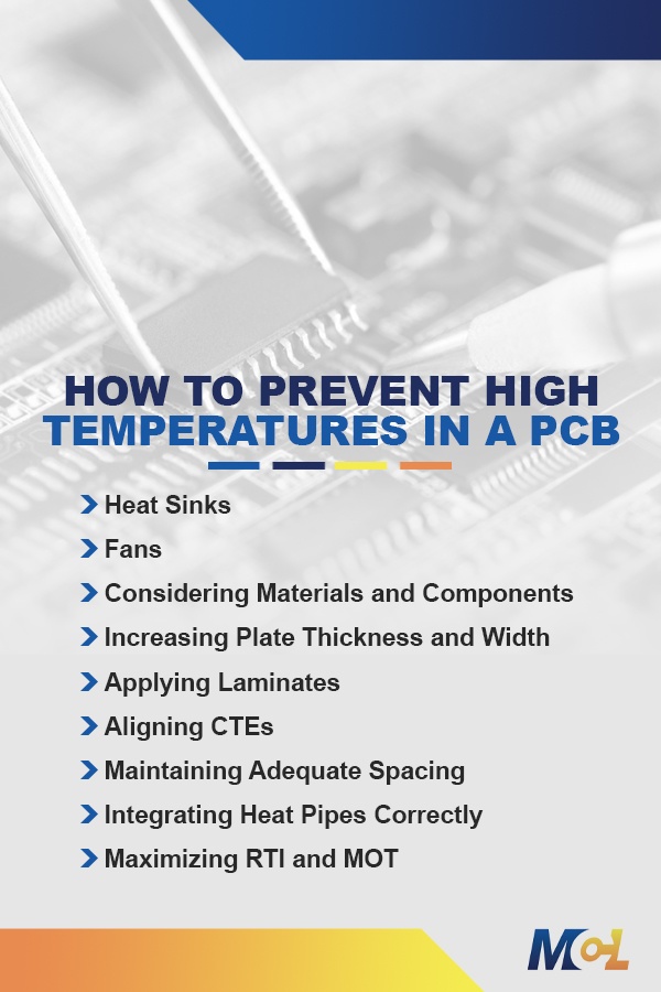
As we have seen, preventing a PCB temperature rise is critical. But how can you reduce heat in a PCB? Engineers can employ a few different PCB heat dissipation techniques:
1. Heat Sinks
A PCB is basically a heat-generating factory because of all the heat-producing components it contains. The PCB needs some way to dissipate all that thermal energy. Generally, the answer involves heat sinks. Heat sinks dissipate the heat safely so it will not build up and damage the board.
2. Fans
Most electronic devices contain fans for cooling, and part of the purpose of those fans is to help cool PCBs. Cooling fans disperse heat out of electronic devices while letting cool air in, helping to prevent overheating and extend the PCB’s lifespan and performance.
3. Considering Materials and Components
Choosing heat-resistant materials one of the most effective strategies for reducing heat in a PCB. For example, heavy copper PCBs constructed with thick copper plates make excellent choices for their durability and ability to withstand high temperatures. They handle higher levels of currents, resist higher temperatures for longer amounts of time and provide for stronger connection points than standard PCBs. For these reasons, they are particularly useful in automotive, aviation, heavy machinery and power converter applications and other heavy-duty environments.
Many PCBs contain FR-4, which, though it is useful as a flame retardant, cannot tolerate extremely high temperatures. Knowing that a PCB contains FR-4 in its construction can allow engineers to design circuits that will not generate more heat than the material can withstand.
Materials such as RF materials — used in radio-frequency circuits — and polyimide are also sensitive to high temperatures. Polytetrafluoroethylene (PTFE) is extremely common in RF boards, but it can smear under the heat of drilling, and the smear is very difficult to remove. These materials are not as common in PCBs as FR-4, but engineers should use caution in their designs if they are working with these materials as well. Making use of a high-temperature laminate in these situations is highly recommended.
4. Increasing Plate Thickness and Width
In PCBs, thicker plates tend to conduct heat less effectively than thinner ones. They require more power to reach high temperatures, so with the right engineering, they can help reduce the risk of overheating, warping and disruption.
5. Applying Laminates
Applying laminates is another way to prevent damage from high temperatures. High-temperature PCB laminates can prevent overheating by offering heat protection for the PCB’s components.
High-temperature laminates should have the following protective properties:
- Glass transition temperature (TG): Glass transition temperature refers to the temperature at which polymers shift thermodynamically from rigid to soft. High-TG PCBs offer superior protection.
- Time to delamination: High heat can delaminate a PCB laminate over time. The best laminates will take a long time to become delaminated at high temperatures.
- Moisture absorption: PCB laminates should have dependable, protective moisture-absorption capabilities. If the PCB will operate in an air-controlled environment like a laboratory, moisture absorption may not be a high priority. But if the PCB will operate in an environment where it may become exposed to the elements, adequate moisture-absorption capabilities are critical.
- Decomposition temperature (TD): Decomposition temperature refers to the temperature at which 5% of the laminate’s mass is lost because of decomposition. A high decomposition temperature offers superior protection.
- Z-axis expansion: Z-axis expansion refers to the expansion of the material along the z-axis as a percentage of the coefficient of thermal expansion. Lower z-axis expansion also offers superior protection.
6. Aligning CTEs
The coefficient of thermal expansion (CTE) measures how much a material expands when exposed to high temperatures. In PCB design, it’s ideal for the dielectric layers to have a similar CTE to that of the copper layers. That way, if the layers expand, they do so in a uniform way that leads to minimal damage.
In a multilayer stack, if CTEs are not aligned, the layers will expand at radically different rates, which can cause warping and disruption. If this uneven expansion occurs during PCB assembly, the misalignments can also cause serious problems for drilling.
Choosing PCB materials with lower CTEs helps prevent overheating. For example, PTFE filled with woven glass or microglass fibers has excellent electrical characteristics, but it also has a high CTE. So this material is a poor choice when thermal toughness is a top priority. On the other hand, PTFE filled with ceramic has a lower CTE and performs much better at high temperatures, though it loses a little in electrical characteristics.
7. Maintaining Adequate Spacing
Determining component spacing on a PCB can be a tricky process. When board components are too close together, crosstalk may result — that is, different components may begin interacting with each other in undesirable ways. These unwanted interactions lead to something known as the skin effect. When the skin effect occurs, trace resistances increase, leading to resistive losses and adding heat to the circuit. The skin effect is particularly common with high-frequency PCBs, so engineers must take extra care with component spacing to keep the boards from overheating.
8. Integrating Heat Pipes Correctly
Heat pipes in a PCB can help disperse heat as well. The liquid in the pipes can absorb heat and prevent it from damaging the components of the board.
9. Maximizing RTI and MOT
Relative thermal index (RTI) and maximum operating temperature (MOT) are two relevant measurements engineers should pay careful attention to in the design of PCBs.
RTI indicates the highest temperature that a material can handle without undergoing changes to its properties or a reduction in its performance. MOT refers to the highest temperature that a particular circuit board configuration can withstand without undergoing changes to its properties or diminution of its performance. Engineers should keep both these measurements in mind in the design of PCBs and choose materials and circuit components with robust heat resistance as determined by these metrics.
Contact MCL for All Your PCB Needs

When you need PCBs designed for temperature control, make Millenium Circuits Limited your trusted provider for engineering solutions. Our high-temperature PCB laminates help reduce the risk of overheating in PCBs, and our heavy copper PCBs and high-TG PCBs offer superior ability to withstand high temperatures. We can also help facilitate the design of custom PCBs to your specifications.
Contact us today for a quote or to learn more.