
Jump To:
What Is FR4 Substrate Material?
Making the Choice: FR4 vs High-Frequency Laminate
Most electrical engineers and individuals involved with printed circuit boards (PCBs) are familiar with the material FR4. FR4 is the backbone material upon which most modern rigid circuit boards are built. However, many are unaware of what FR4 is, let alone why it is the most popular PCB base.
Read on to learn more about FR4 printed circuit boards, such as what they are, why they are so popular and how FR4 PCB specifications compare to other options within the industry.
What Is FR4 Material in PCB?
FR4, also written as FR-4, is both a name and a standard rating. The name is applied to the fiberglass-reinforced epoxy-laminated sheets used in printed circuit board manufacturing. “FR” stands for flame retardant, and “4” references the spec temperature range the material is guaranteed to work in.
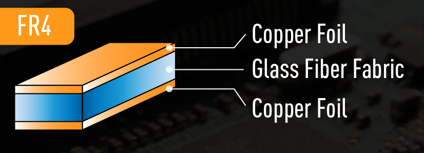
The material widely referred to as FR4 is a composite structure. The most basic layer of the material is fiberglass woven into a thin, cloth-like sheet. The fiberglass gives FR4 its necessary structural stability. This innermost fiberglass layer is then surrounded and bound by a flame-resistant epoxy resin. This composite is what gives the material rigidity, among its other physical properties. FR4 provides a balance of properties, including good electrical insulation, mechanical strength, flame resistance, and ease of manufacturing. It’s a versatile and cost-effective choice for a wide range of PCB applications.
There are four other FR ratings, each of which corresponds to a specific grade of PCB substrate with differing properties. FR4 is the most popular at present, as many are obsolete. However, new substrates are on the horizon, some of which promote sustainability in ways standard FR4 substrates can’t.
The other FR ratings include:
- FR1: This substrate was used in early radios and other consumer electronics. It was made of paper and phenolic resin and had limited temperature resistance capabilities. As technology evolved, FR1 PCBs were phased out due to this limitation and their relatively high rate of signal loss.
- FR2: This substrate overtook the FR1 substrate due to its increased mechanical stability and temperature resistance. Both traits are owed to the mixture of cotton paper and phenolic resin that make up the substrate, though these materials didn’t improve much on signal loss rate relative to FR1 PCBs. FR2 PCBs were used by the aerospace sector and in many industrial processes during the 1950s and ’60s, but they were largely phased out by the 21st century.
- FR3: The first two PCB substrates used paper as the base of their design, but FR3 PCBs made a significant step forward by using woven fiberglass instead. Epoxy resin was also used over phenolic resin. Together, these materials gave FR3 substrates highly stable electrical properties, increased component densities, and higher-speed signals. They’re also more flame-retardant than their predecessors. Today, you may encounter these substrates in older industrial electronics and devices.
- FR5: PCBs with FR5 substrates are at the cutting edge of electronics. FR4s are the most common substrate type in the world today, but FR5s are the future of this technology. They’re already being used in the aerospace and military sectors due to their extreme temperature resistance capabilities and high signal integrity. As with FR3 PCBs, FR5 PCBs use woven fiberglass as a base. However, they use high glass transition epoxy resin instead of a more basic epoxy resin.
FR4 sheets are widely popular among electrical engineers and designers as a PCB substrate material. The low cost and versatility of the material, as well as its wealth of beneficial physical properties, account for that popularity. FR4 sheets are electrical insulators with high dielectric strength. They also feature a high strength-to-weight ratio and are lightweight and resistant to moisture. Add this to their relative temperature resistance and glassing temperature, and FR4 material can perform well in most environmental conditions.
Request a Free Quote Call 717-558-5975
How Is FR-4 Used in PCBs?
These qualities make FR4 an ideal default substrate material for quality PCB manufacturing processes. When used appropriately, these properties can also form the foundations of high-quality and low-cost PCBs. FR4 PCB design is a complex process, but when used properly, these substrates have a range of functions.
Within a PCB, FR4 forms the primary insulating backbone. This is the base upon which the manufacturing company builds the circuit for a given function. Once prepared, the FR4 circuit board is laminated with one or more layers of copper foil using heat and adhesive. This copper forms the traces in the finished product and may cover one or both sides, depending on the design of the board.
Complex PCBs may use more than one side or even layer the circuit board to produce more sophisticated circuits that can power more complex technologies. From here, the circuits are drawn and etched out before being covered with a solder mask layer, preparing the board for the final silkscreen layer and the subsequent soldering process.
How to Determine FR4 Thickness for PCB Design
When ordering a laminate board for a PCB project, the designer or electrical engineer must specify the FR4 thickness. This is measured in inch-based units, such as the thousandth of an inch, or thou, or millimeters, depending on which is most appropriate for the setting. The thickness of a sheet of FR4 ranges widely depending on the needs of the project, but it tends to range from ten thou to three inches.
While board thickness may not seem like a significant factor in the design of a PCB, in reality, it is an essential feature. Board thickness affects several aspects of the board’s functionality, which is why several factors are considered in determining the thickness of a board for design. These include the following.
1. Space: Thinner May Be Better
If space concerns the designer, a thinner FR4 board tends to be preferable. This is a predominant factor for the manufacture of smaller devices, like USB connectors and many Bluetooth accessories. Even for larger projects, smaller FR4 PCBs tend to be favored to save space within the device.
In many cases, however, thicker FR4 boards are needed for more sophisticated technologies. These thicker boards can support grooves that thinner boards can’t, opening up new design avenues for electrical engineers. Physical strength and durability are also major factors.
2. Connections: The Wrong One Could Result in Damage
A two-sided PCB design requires an edge connector or a plated-through hole to join the two sides. This can be a major limiting factor for the final size of the PCB since PCB edge connectors only fit a particular set of PCB thicknesses. The mating portion of a connector has to fit snugly on the side of the PCB, or else risk slippage or damage to the PCB. This is one of the primary reasons why circuit design comes before choosing materials for the circuit.
3. Impedance Matching: Essential to Maintaining Board Function
Every multi-layered board acts as a capacitor on adjacent layers. This is why the thickness of this board is so important — the thickness of the FR4 PCB material determines the thickness of the dielectric, which in turn affects the value of the capacitance.
This is an especially key factor for some high-frequency PCBs, such as RF and microwave PCBs. High-frequency designs focus on impedance matching as an essential component to maintain optimal board function, so getting the right capacitance for each layer is crucial.
4. Flexibility: Depends on the Application
Thinner boards can flex in some capacity. While an unusual trait, flexibility can be a positive or negative feature, depending on the application.
More flexible boards tend to be preferable in some applications where the product is regularly stressed or flexed. For example, those using boards for medical and automotive applications often prefer flexible boards due to the constant stress and flexing to which these PCBs are often subjected.
However, flexibility can be a detriment to the PCB manufacturing process, resulting in serious problems later in assembly. When handled by a machine, a more flexible board may flex when dealt with by a soldering machine, causing the component to be soldered at an angle. Additionally, this flexing has the potential to break freshly placed components and connections already on the board. It’s important to know the operational environment to a greater degree than normal.
5. Design Requirements: Intended Use Impacts FR4 Thickness
Thin boards aren’t preferable in all cases, primarily due to the limitations thin boards put on PCB plans. Thin FR4 boards can’t feasibly feature grooves, and they can’t be too large without risking fracture. Thicker boards, however, can accomplish both. Always account for this when weighing FR4 thicknesses against one another.
6. Component Compatibility: Some May Only Work With a Small Range of Thicknesses
The thickness of a board can also affect the compatibility of components with the board. Just like edge connectors, many components work with a small range of board thicknesses. This is especially true for some through-hole components, for example. The components of the PCB must be considered before a substrate thickness is selected.
7. Weight: Lighter Products May Be More Attractive
The FR4 thickness will, logically, affect the weight of the final PCB. While weight is less of an issue in some applications, it is often a consideration in consumer electronics. Lighter PCBs make for lighter products, which makes them cheaper to ship and, in some cases, more attractive to consumers. Phones, for example, need to be compact and easy to handle for long periods, so lightweight FR4 substrates are a must.
When should you to use FR4?
Many electronics applications choose to use the epoxy-based FR4 board. Their strength, reliability and relatively low cost make FR4 epoxy substrates a logical default choice for electronics engineers. However, FR4 isn’t ideal for all situations, especially high-frequency designs. For these designs, high-frequency laminates tend to be a more common choice.
Choosing between these materials may be difficult, which is why we list more detailed guidelines below.
When trying to decide whether to build a PCB with FR-4 or a high-frequency laminate, consider the following key features of each.
Cost: FR4 Will Be Cheaper
FR4 material is a very common PCB base, primarily due to its relatively low cost. High-frequency laminates, on the other hand, are considerably higher in price, which is a significant drawback for cost-concerned designers and manufacturers. This is the primary limiting factor for companies when choosing between FR4 and high-frequency laminates. In some cases, however, the investment may be worth the additional cost. It all depends on the end product.
Signal Loss: Lower DF Leads to Lower Signal Loss
Signal loss is, in many cases, a critical part of a PCB design, especially in high-frequency situations where signal loss is more of a problem. For these designs, FR4 is not an ideal choice — FR4 has a higher DF, or dissipation factor, than high-frequency laminates. This means FR4 circuits will suffer more signal loss than an identical circuit on a high-frequency laminate.
The DF of FR4 is around 0.020, while the DF of most high-frequency laminates is around 0.004, a fifth of FR4’s DF. The lower the DF, the less signal loss overall. The other issue is that the DF of FR4 increases as a signal’s frequency increases, meaning that as the frequency of the signal increases, more signal loss occurs. Since high-frequency laminates have more stable DF characteristics, they experience less loss at higher frequencies.
Impedance Stability: Dk Stability Matters
Stable impedance is another important factor for many designs, as it often means more predictable performance, especially for larger circuits or high-frequency designs. Again, in this area, FR4 and high-frequency laminates offer different results. Maintaining stable impedance requires a material to maintain a stable Dk, or dielectric constant, across the entire material as the temperature of the material changes.
In this regard, FR4 is not a suitable material for maintaining stable impedance, as its Dk value varies widely within a single board and as the temperature of the board changes. High-frequency laminates don’t have Dk values that vary as widely, remaining fairly constant across the area of a board as temperature changes.
Temperature Management: Lower Thermal Coefficient Leads to Stability
Temperature performance is another factor to consider when choosing between an FR4 board or high-frequency laminate for a PCB base. When comparing temperature performance, the thermal coefficient of dielectric constant provides a decent gauge. This number measures how much a material’s dielectric constant changes with temperature:
- For FR4, this value rests around 200 parts per million per degree Celsius change in temperature
- High-frequency laminates feature a thermal coefficient of dielectric constant of around 40 parts per million per degree Celsius.
Though both may seem like small numbers, they offer widely different results. The significant coefficient of FR4 means an FR4 board’s Dk may vary considerably across its area. In comparison, the lower coefficient for high-frequency laminates indicates less variation in temperature across the board’s area. This is particularly important to consider when designing boards intended for hotter environments.
Dielectric Constant: Choose the Right Dk Value
Sometimes a circuit board’s dielectric constant can be just as important as the other features of the board. The dielectric constant of a circuit board impacts the size of a circuit’s transmission lines, especially in high-frequency circuits like RF or microwave designs. The smaller the transmission lines can be, the smaller the circuit itself.
Therefore, if a smaller circuit board size is desirable, a board material with a higher Dk value is the best choice. FR4 features a dielectric constant of about 4.5, which is lower than high-frequency materials’ Dk, which usually lies around 6.15 to 11. Using these high-value Dk materials can have significant results, shaving 25 percent or more off the size of the final circuit board.
Operational Environment: Heat and Moisture Resistance Matter
The operational environment for the circuit is yet another thing to keep in mind when choosing between an FR4 and a high-frequency laminate board. This includes the environmental conditions, like moisture and temperature. In both cases, high-frequency laminates provide more moisture and heat resistance than FR4, meaning the operational environment will have significantly less impact on the function of the circuit. This is a critical consideration if the PCB will operate in outdoor or extreme industrial environments.
In short, high-frequency laminates feature a wide range of physical characteristics, many of which are superior to FR4. The only drawback high-frequency laminates have is their relatively higher cost, which is a significant factor for cost-focused designers. The big decision, then, is deciding when the advantages outweigh the costs of high-frequency laminates.
Making the Choice: FR4 Versus High-Frequency Laminate
So, using all the information listed above, how can an electric engineer or PCB designer choose between FR4 and a high-frequency laminate? First, the designer must list and compare the electrical and mechanical requirements for the final PCB, using the most specific parameters as possible. The designer must then examine how well FR4 will meet these parameters as compared to a laminate designed to handle high-frequency signals. More precise data for each of the points above is readily available using industry data sheets.
In short, FR4 is a widely relevant material, popular mostly for its low cost and relative mechanical and electrical stability. While FR4 material features extensive benefits and is available in a variety of thicknesses and sizes, it isn’t the best choice for every application, especially high-frequency applications like RF and microwave designs. In these latter cases, a high-frequency laminate is the better choice. Still, it’s easy to see why FR4 is still in such common use to this day.
Why Trust Us
Millennium Circuits Limited has been in the PCB business for two decades. We have a range of certifications, including ISO, IPC, and UL certifications. We’ve done the work to ensure we’re compliant with regulations across the board.
We work closely with FR4 substrates, laminates, and circuit board design every day. From engineering to manufacturing and beyond, we’re acquainted with every aspect of the PCB life cycle. Companies in the medical, automotive, and defense industries trust us to get the job done.

Contact Millennium Circuits Limited Today
If you’re looking for FR4 printed circuit boards or boards of any other material, Millennium Circuits Limited can help. MCL supplies high-quality boards and circuits in any quantity while maintaining extreme quality and on-time delivery. Since 2005, our Harrisburg, PA, business has prided itself on providing high-quality services that comply with the highest international standards. We even offer engineering support and a competitive pricing schedule.
See why MCL rates 98 percent approval in quality and 99 percent approval in delivery performance. Contact us today for a fast, no-obligation quote to learn how MCL can help you.
Request a Free Quote Call 717-558-5975